引き続きUser’s Guideを読んでいきます。
8ページからの内容となります。
前回の記事はこちら。
今回はModelica標準ライブラリ、DCモータのサンプルを使ってみます。
急にMBDっぽい内容ですね。
dcmotor.moはバージョン3.2.2のようですが3.2.3にも互換性があるようです。
現段階では細かいことはよくわかりません。。。
>> loadModel(Modelica, {"3.2.3"})
true

>> loadFile(getInstallationDirectoryPath() +"/share/doc/omc/testmodels/dcmotor.mo")
true
"Notification: dcmotor requested package Modelica of version 3.2.2. Modelica 3.2.3 is used instead which states that it is fully compatible without conversion script needed.
"
simulateでシミュレーションができるようです。この例では0~10s間の計算を実行。
計算に6.4719391sかかったということっぽい。
>> simulate(dcmotor, startTime=0.0, stopTime=10.0)
record SimulationResult
    resultFile = "C:/Users/[ユーザ名]/AppData/Local/Temp/OpenModelica/dcmotor_res.mat",
    simulationOptions = "startTime = 0.0, stopTime = 10.0, numberOfIntervals = 500, tolerance = 1e-06, method = 'dassl', fileNamePrefix = 'dcmotor', options = '', outputFormat = 'mat', variableFilter = '.*', cflags = '', simflags = ''",
    messages = "LOG_SUCCESS       | info    | The initialization finished successfully without homotopy method.
LOG_SUCCESS       | info    | The simulation finished successfully.
",
    timeFrontend = 0.0887131,
    timeBackend = 0.0223541,
    timeSimCode = 0.0078872,
    timeTemplates = 0.0127341,
    timeCompile = 1.8318949,
    timeSimulation = 4.5081214,
    timeTotal = 6.4719391
end SimulationResult;
"Notification: Modelica requested package Complex of version 3.2.3. Complex 4.0.0 is used instead which states that it is fully compatible without conversion script needed.
Notification: Modelica requested package ModelicaServices of version 3.2.3. ModelicaServices 4.0.0 is used instead which states that it is fully compatible without conversion script needed.
Notification: dcmotor requested package Modelica of version 3.2.2. Modelica 3.2.3 is used instead which states that it is fully compatible without conversion script needed.
"
listでモデルの内容をまとめてくれそうです。
>> list(dcmotor)
"model dcmotor
  import Modelica.Electrical.Analog.Basic;
  Basic.Resistor resistor1(R = 10);
  Basic.Inductor inductor1(L = 0.2, i.fixed = true);
  Basic.Ground ground1;
  Modelica.Mechanics.Rotational.Components.Inertia load(J = 1, phi.fixed = true, w.fixed = true);
  Basic.EMF emf1(k = 1.0);
  Modelica.Blocks.Sources.Step step1;
  Modelica.Electrical.Analog.Sources.SignalVoltage signalVoltage1;
equation
  connect(step1.y, signalVoltage1.v);
  connect(signalVoltage1.p, resistor1.p);
  connect(resistor1.n, inductor1.p);
  connect(inductor1.n, emf1.p);
  connect(emf1.flange, load.flange_a);
  connect(signalVoltage1.n, ground1.p);
  connect(ground1.p, emf1.n);
  annotation(
    uses(Modelica(version = \"3.2.2\")));
end dcmotor;"
instantiateModelでソースコードが表示されるのかな?
下記は長いので一部だけを抜粋です。
>> instantiateModel(dcmotor)
"class dcmotor
  parameter Real resistor1.R(quantity = \"Resistance\", unit = \"Ohm\", start = 1.0) = 10.0 \"Resistance at temperature T_ref\";
  parameter Real resistor1.T_ref(quantity = \"ThermodynamicTemperature\", unit = \"K\", displayUnit = \"degC\", min = 0.0, start = 288.15, nominal = 300.0) = 300.15 \"Reference temperature\";
  parameter Real resistor1.alpha(quantity = \"LinearTemperatureCoefficient\", unit = \"1/K\") = 0.0 \"Temperature coefficient of resistance (R_actual = R*(1 + alpha*(T_heatPort - T_ref))\";
  Real resistor1.v(quantity = \"ElectricPotential\", unit = \"V\") \"Voltage drop of the two pins (= p.v - n.v)\";
  Real resistor1.i(quantity = \"ElectricCurrent\", unit = \"A\") \"Current flowing from pin p to pin n\";
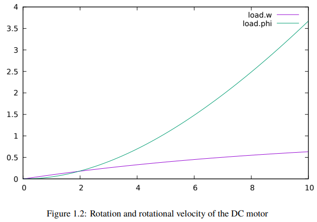
結果をplotした結果がUser’s Guideには載っていますが、作り方がわからないのでまた追々、、、
こちらがUser’s Guideのグラフ

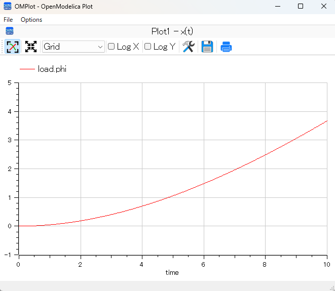
想像でplot(load.w)を実行してみたらOMPlotでグラフが作成されましたが、重ね書きの方法がわかりませんでした。

今回はここまでにします。
DCモータに関するシミュレーションを実行し、実用に近づいてきました。


コメント